We have intercepted an encrypted message with critical information, and also managed to recover the machine that is able to decrypt it, with a copy of the source program it should run to decrypt the message. The crazy scientist that built this machine was accidentally killed during the extraction. It’s a very elaborate mechanical machine with tons of pipes and valves but we managed to reverse-engineer its logic and build a simulation out of it, but now we need to convert the source of the program into something that the machine is able to understand and execute! The encrypted message is already loaded into the simulation.
Category: hardware
Solver: rgw, nh1729
Flag: HTB{f1rm_15_b3tw33n_h4rd_4nd_50ft}
Writeup
Circuit Analyis
In this challenge, we get four files: A Logisim circuit file cpu.circ, an example assembly file example.asm with associated binary example.data as well as an assembly file program.asm. This is what example.asm looks like:
:start
        movl ax, 10
:sub1
        movl bx, 1
        sub  bx
        cmp  ax,  ax
        movl bx,  :sub1
        jnz
        rst
This is what example.data looks like:
v2.0 raw
10000a 100101 10100 130000 100101 e0000 40000
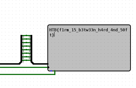
When we open the circuit file in Logisim Evolution ([1]), we see a CPU circuit which is divided into subcomponents:
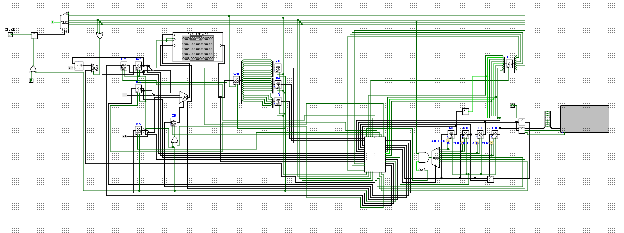
The CPU contains some RAM, registers and a terminal device. The task is now to assemble program.asm into the binary instructions that the CPU reads from RAM. There is a “network device” with some read-only memory. This memory will be decrypted by the assembled program.
The first step was to figure out the instruction format. Upon inspecting the RAM, we found a word size of 21 bits. When looking at the instruction register (IR) and operand registers (RA, RB), we noticed that the opcode with is 5 bit and each operand has a width of 8 bit:
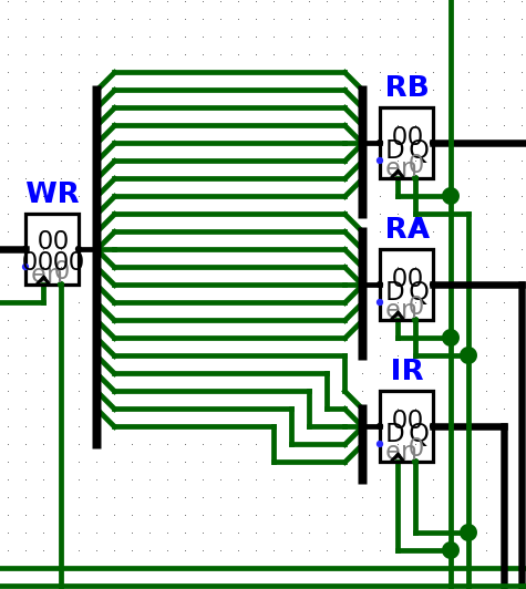
Therefore, we can calculate instruction = (ir<<16) | (ra<<8) | rb.
Next, we inspected the assembly code. There, we saw that commands can take integer constants or one of four general-purpose-registers ax, bx, cx or dx. By looking at the circuit, we could associate each instruction with an opcode. These were either visible in the components themselves or via the wiring to a multiplexer:
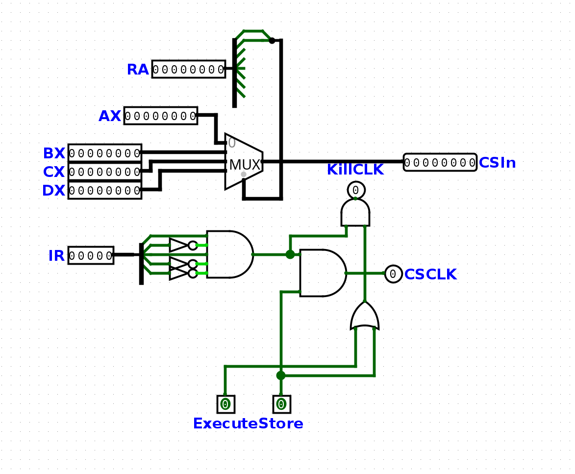
Since the components were all labeled, we could extract a complete opcode table from the circuit file. The next step was to write an assembler that converts our input program into the respective opcodes.
Writing an assembler
We decided to write our assembler in python. To parse the asm files, we first defined dictionaries with all required symbols:
OPCODES = {
	'add'	: 0b00000,
	'sub'	: 0b00001,
	'mul'	: 0b00010,
	'clr'	: 0b00011,
	'rst'	: 0b00100,
	'jmp'	: 0b00101,
	'ljmp'	: 0b00110,
	'jlp'	: 0b00111,
	'jg'	: 0b01000,
	'jge'	: 0b01001,
	'jl'	: 0b01010,
	'jle'	: 0b01011,
	'je'	: 0b01100,
	'jz'	: 0b01101,
	'jnz'	: 0b01110,
	'mov'	: 0b01111,
	'movl'	: 0b10000,
	'call'	: 0b10001,
	'ret'	: 0b10010,
	'cmp'	: 0b10011,
	'push'	: 0b10100,
	'pop'	: 0b10101,
	'div'	: 0b10110,
	'mmiv'	: 0b10111,
	'mmov'	: 0b11000,
	'msk'	: 0b11010,
	'mskb'	: 0b11011,
}

REGISTERS = {
	'ax': 0,
	'bx': 1,
	'cx': 2,
	'dx': 3
}
Then, we build our main assembler function. For assembling, we have to keep track of all labels in the code. We decided to collect all labels using a virtual instruction pointer before starting to build the output so labels could be referenced globally in the assembler code.
def compile(s):
	lines = s.split('\n')
	output = []
	labels = {}

	# scan labels
	ip = 0
	for line in lines:
		if line.strip().startswith(':'):
			labels[line] = ip
		else:
			ip += 1
In the main loop over all instructions, we skipped labels and empty lines, and then combined the up to two operands together with the opcode into the full instruction.
for line in lines:
	line = line.strip()

	if len(line) == 0:
		continue

	tokens = [l for l in line.split() if len(l) > 0]

	if tokens[0].startswith(':'):
		continue

	opcode = OPCODES[tokens[0]]
	ra = 0
	rb = 0

	if len(tokens) > 1:
		ra = resolve_symbol(tokens[1].replace(',',''),labels)
	if len(tokens) > 2:
		rb = resolve_symbol(tokens[2].replace(',',''),labels)

	instruction = (opcode << 16) | (ra << 8) | rb

	output.append(instruction)
To resolve registers, constants and symbols as operands correctly, we extracted a simple function for that:
def resolve_symbol(s,labels):
	if s.startswith(':'):
		if '+' in s:
			l,o = s.split('+')
			return labels[l] + int(o,0)
		return labels[s]
	if s in REGISTERS:
		return REGISTERS[s]
	return int(s,0)
As a side note, in line 53 in the program.asm file, a label is referenced without a colon.
movl bx, sub5
Instead of writing more robust code, we fixed this by hand in the asm file. Finally, we only had to call our function and print the output in a format that can be pasted into the RAM component in logisim.
f = open('program.asm')
s = f.read()
f.close()

for a in compile(s):
	print(hex(a)[2:], end=' ')
print()
This produced the final machine code.
10020a 30000 100101 100300 170003 10012e 110100 180000 100137 110100 100101 100300 140300 100137 110100 100101 10100 130000 10010a e0000 10012e 110100 100100 170101 170201 150000 100101 100300 100137 110100 180101 1a0000 170101 180102 1b0000 170201 1000ff 130100 100119 a0000 100100 180301 100201 100200 100116 50100 100005 100137 110100 100101 10100 130000 10012f e0000 120000 100204 100200 120000
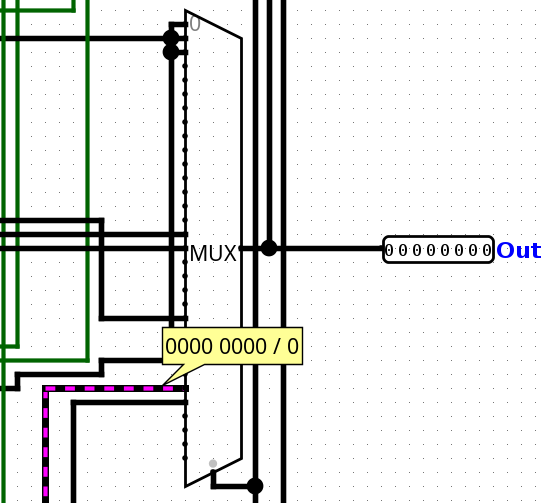
After inserting the code into the virtual processor, we started the simulation. First, we thought we made a mistake as the processor ran without output on the display element. Inspecting the memory, we saw the process indeed writing bytes in the range beginning at 0xfe000000. After one minute and twenty seconds on maximum simulation frequency, the flag was printed slowly but surely onto the display:
In total, it took more than 3 minutes to print the flag.
Solver
OPCODES = {
	'add'	: 0b00000,
	'sub'	: 0b00001,
	'mul'	: 0b00010,
	'clr'	: 0b00011,
	'rst'	: 0b00100,
	'jmp'	: 0b00101,
	'ljmp'	: 0b00110,
	'jlp'	: 0b00111,
	'jg'	: 0b01000,
	'jge'	: 0b01001,
	'jl'	: 0b01010,
	'jle'	: 0b01011,
	'je'	: 0b01100,
	'jz'	: 0b01101,
	'jnz'	: 0b01110,
	'mov'	: 0b01111,
	'movl'	: 0b10000,
	'call'	: 0b10001,
	'ret'	: 0b10010,
	'cmp'	: 0b10011,
	'push'	: 0b10100,
	'pop'	: 0b10101,
	'div'	: 0b10110,
	'mmiv'	: 0b10111,
	'mmov'	: 0b11000,
	'msk'	: 0b11010,
	'mskb'	: 0b11011,
}

REGISTERS = {
	'ax': 0,
	'bx': 1,
	'cx': 2,
	'dx': 3
}

def compile(s):
	lines = s.split('\n')
	output = []
	labels = {}

	# scan labels
	ip = 0
	for line in lines:
		if line.strip().startswith(':'):
			labels[line] = ip
		else:
			ip += 1

	for line in lines:
		line = line.strip()

		if len(line) == 0:
			continue

		tokens = [l for l in line.split() if len(l) > 0]

		if tokens[0].startswith(':'):
			continue

		opcode = OPCODES[tokens[0]]
		ra = 0
		rb = 0

		if len(tokens) > 1:
			ra = resolve_symbol(tokens[1].replace(',',''),labels)
		if len(tokens) > 2:
			rb = resolve_symbol(tokens[2].replace(',',''),labels)

		instruction = (opcode << 16) | (ra << 8) | rb

		output.append(instruction)
	return output

def resolve_symbol(s,labels):
	if s.startswith(':'):
		if '+' in s:
			l,o = s.split('+')
			return labels[l] + int(o,0)
		return labels[s]
	if s in REGISTERS:
		return REGISTERS[s]
	return int(s,0)


f = open('program.asm')
s = f.read()
f.close()

for a in compile(s):
	print(hex(a)[2:], end=' ')
print()