During the attempt to exploit a secure crypto-processor we identified some embedded logic in it. We were able to recreate the logic diagram and make a block diagram to map its connections to the original circuit. We need to identify its use, which may lead to compromising the chip.
Category: Hardware
Solver: davex
Writeup
We first looked up the content of the challenge website is. When you entered the website you could saw a diagram of the system described in the description.
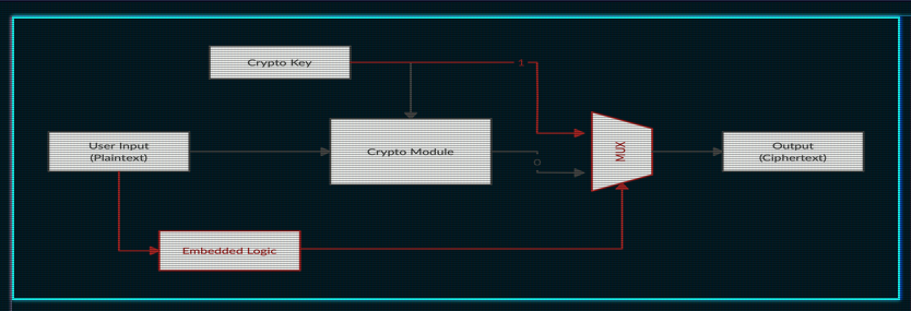
The goal of this attack should obviously be to get the output of the embedded logic to 1 to receive the crypto key. As also described in the description we received the block diagram of the embedded logic.

Because the diagram has many components and connections we will highlight the important parts. Because of the complexity and size of the diagram we quickly decided to rebuild the whole system in a program called logisim [1]. With this software, we could simulate the behavior of this system. After we rebuild [2] the whole system we discovered the system and learned the following facts about it.
First, we looked up what the reset handler does.
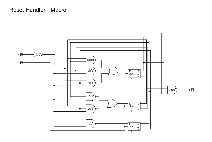
This is a counter which counts until eight clock cycles and after that, it has a value of 1.
After that, we looked up the big and complex part of the diagram but we realized that this is just like a huge encoder of our input string which is controlled by the following part of the diagram.
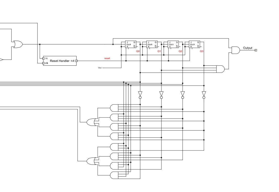
That JK Flipflops on the right upper corner simply build a counter. They can be reset by the reset handler. The goal of our input should be that all of these JK Flip flops reach all the status 1 at the same time. Because it’s a counter we cannot let these JK Flipflops reset themselves by the reset handler.
We ended up with the following control mechanisms to get the valid input string bit by bit.
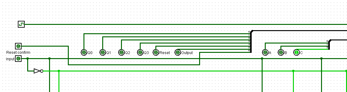
To receive the flag we simply needed to set the input to 0 or 1 and look up if any of our variables (a,b,c) would be 1 after the next clock cycle. If not we know we gave an invalid input. If any of these variables would be 1 it’s a valid input. The only difference in each character is the last bit. This bit is controlled by the reset handler. If our input will trigger the reset handler in the next clock cycle we need to invert it. With this, we finally received the full bit string by hand
01001000 01010100 01000010 01111011 00110111 01110010 00110001 00110110 00110110 00110011 00110011 00110011 00110011 01110010 01100100 01111101
We wrote a simple script which transforms this bitstring into the ascii string
def bits2string(b):
    b = b.replace(" ", "")
    return ''.join(chr(int(''.join(x), 2)) for x in zip(*[iter(b)]*8))

def main():
    flag_bits = "01001000 01010100 01000010 01111011 00110111 01110010 00110001 00110110 00110110 00110011 00110011 00110011 00110011 01110010 01100100 01111101"
    print("Flag: " + bits2string(flag_bits))

if __name__ == "__main__":
    main()
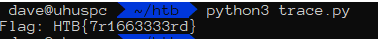
HTB{7r1663333rd}
Other resources
[1] http://www.cburch.com/logisim/de/index.html
[2] The logisim file contained in the writeup submission